
目次
1. MPU-6050を使って1軸の値を取得してみよう!
1.1 材料
- Arduino Nano
- ブレッドボード
- USBケーブル
- MPU6050
- ジャンパーワイヤ
MPU6050は、加速度センサとジャイロスコープ(角速度センサ)を一体化したセンサです。このデバイスは、3軸(x,y,z軸)の加速度と3軸(x,y,z軸)の角速度の両方を測定できるため、6軸慣性センサとも呼ばれます。このセンサは、モーショントラッキングや位置追跡に使用される他、スマートフォン、タブレット、ドローン、ロボットなど、さまざまなデバイスに搭載されています。
現実世界の動きと加速度、ジャイロと理解するにはこちらの動画がわかりやすいです。時間ある際に覗いてみてください。
加速度センサの原理
加速度センサは様々な種類が存在しますが、ピエゾ抵抗型について簡単に説明します。加速度センサにはピエゾ抵抗と呼ばれる抵抗が使われていて、力が加わるとその抵抗値が変化する性質を持っています。
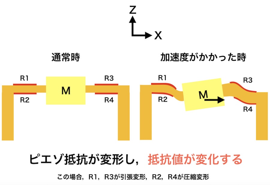
- 図の左側では、加速度がかかっていない通常の状態が示されています。この状態では、抵抗R1、R2、R3、R4に大きな変化はありません。ピエゾ抵抗は安定しており、抵抗値も変わりません。
- 図の右側では、加速度がかかったときの様子が示されています。加速度がかかると、質量Mが動き、それに伴って抵抗R1、R3が引っ張られ、R2、R4が圧縮されます。
- R1とR3 は引っ張られることで抵抗値が増加し、R2とR4 は圧縮されることで抵抗値が減少します。
このように、加速度がかかることで各抵抗の値が変化し、その変化を電気信号として検出することで、加速度の大きさや方向を計測することができます。
ジャイロセンサの原理
ジャイロセンサは、物体の回転や傾きを検出するセンサです。基本的な原理は、回転する力(角速度)を検出することにあります。内部にある小さな振動体が回転することで、その動きを電気信号に変換し、回転の方向や速度を測定します。
詳しくはこちらがわかりやすいです。
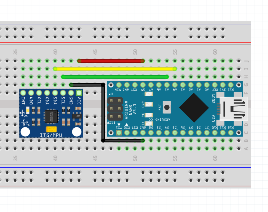
1.2 ブレッドボード図
それでは、以下のようにMPU-6050とArduinoを繋げてみましょう。
| MPU-6050 | Arduino |
| GND | GND |
| VCC | 5V |
| SDA | A4 |
| SCL | A5 |
実際の写真は以下の通り。
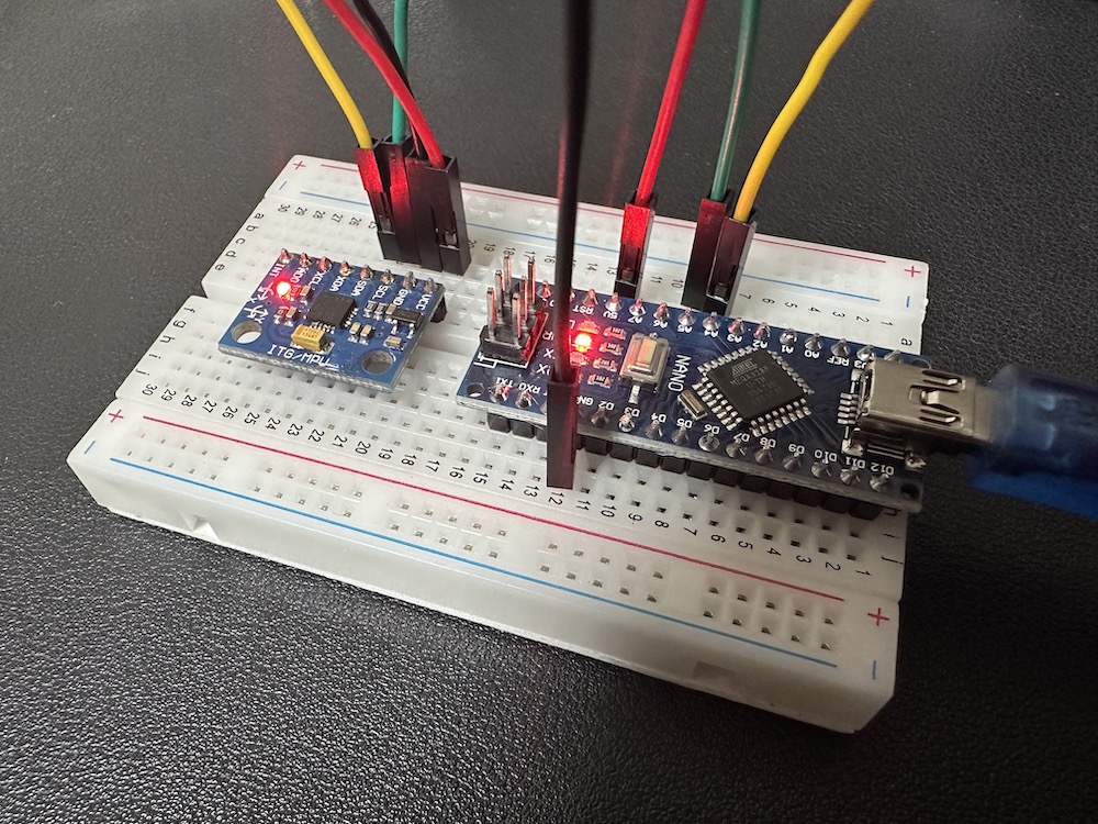
注:加速度センサを折り曲げる必要はありません。挿さればそれでOKです。
1.3 コード
Arduinoのコードは以下の通り。忘れず書き込みましょう。
//S0211_SAMPLE01
#include <Wire.h>

volatile uint8_t data[14]; //センサからのデータ格納用配列
volatile int16_t ax = 0;   //出力データ(生値)

void setup() {
  Serial.begin(9600);//シリアル通信を開始する
  Wire.begin();//I2C通信を開始する

  Wire.beginTransmission(0x68);//送信処理を開始する(0x68がセンサーのアドレス)
  Wire.write(0x6b);            //レジスタ「0x6b」(動作状変数)を指定
  Wire.write(0x00);            //0x00を指定(ON)
  Wire.endTransmission();      //送信を終了する
}

void loop() {
  MPU_DATAGET();
  Serial.print("ax: ");
  Serial.println(ax);
  delay(100);
}

void MPU_DATAGET() {
  Wire.beginTransmission(0x68); //送信処理を開始する
  Wire.write(0x3b);             //(取得値の先頭を指定)
  Wire.endTransmission();       //送信を終了する
  Wire.requestFrom(0x68, 14);   //データを要求する(0x3bから14バイトが6軸の値)

  uint8_t i = 0;
  while (Wire.available()) {
    data[i++] = Wire.read();//データを読み込む
  }


  ax = (data[0] << 8) | data[1];//LowとHighを連結して、値を取得する

}
それでは値をSerial Monitorで確認してみましょう!
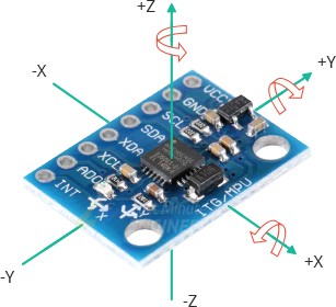
センサをx方向に振ってみるとx軸の加速度データが取れていることを確認できましたか?y方向やz方向に振るとあまり値が変化しないかと思います.(注:加速度値なため回転は取れません。)
(注意):出力に文字列「ax:」が含まれるためSerial Plotterは起動しても反応しません!
2. MPU-6050を使って6軸の値を取得してみよう!
参考:MPU6050をArduinoで使う②6軸分のデータを取得する
2.1 コード
1章と同様の回路構成のまま、コードのみ以下のように変更し、再度書き込みましょう。
//MPU6050 6軸分の角度・角速度を取得するサンプル
#include <Wire.h>

#define ACC_RATE_2G 1671.8 // 加速度(2G)用の変換係数(生値→[m/s2]) ※32767/2/9.8
#define GYO_RATE_250 131.1 // 角速度(250[deg/s])用の変換係数(生値→[deg/s]) ※32767/250

volatile uint8_t data[14]; //センサからのデータ格納用配列

volatile float ax = 0;   //出力データ(X軸加速度)
volatile float ay = 0;   //出力データ(Y軸加速度)
volatile float az = 0;   //出力データ(Z軸加速度)

volatile float rx = 0;   //出力データ(X軸角速度)
volatile float ry = 0;   //出力データ(Y軸角速度)
volatile float rz = 0;   //出力データ(Z軸角速度)

void setup() {
  Serial.begin(9600);//シリアル通信を開始する
  Wire.begin();//I2C通信を開始する

  i2cWriteReg(0x68,0x6b,0x00); //センサーをONにする
  i2cWriteReg(0x68,0x1b,0x00); //角速度レンジ設定(±250[deg/s])
  i2cWriteReg(0x68,0x1c,0x00); //加速度レンジ設定(±2G)

}

void loop() {
  MPU_DATAGET();
  Serial.print("ax: ");
  Serial.print(ax);

  Serial.print("\tay: ");
  Serial.print(ay);

  Serial.print("\taz: ");
  Serial.print(az);


  Serial.print("\trx: ");
  Serial.print(rx);

  Serial.print("\try: ");
  Serial.print(ry);

  Serial.print("\trz: ");
  Serial.println(rz);
  delay(100);
}

void MPU_DATAGET() {
  Wire.beginTransmission(0x68); //送信処理を開始する
  Wire.write(0x3b);             //(取得値の先頭を指定)
  Wire.endTransmission();       //送信を終了する
  Wire.requestFrom(0x68, 14);   //データを要求する(0x3bから14バイトが6軸の値)

  uint8_t i = 0;
  while (Wire.available()) {
    data[i++] = Wire.read();//データを読み込む
  }


  ax = (float)((data[0] << 8) | data[1])/ACC_RATE_2G;//LowとHighを連結して、値を取得する
  ay = (float)((data[2] << 8) | data[3])/ACC_RATE_2G;//LowとHighを連結して、値を取得する
  az = (float)((data[4] << 8) | data[5])/ACC_RATE_2G;//LowとHighを連結して、値を取得する

  rx = (float)((data[8] << 8) | data[9])/GYO_RATE_250;//LowとHighを連結して、値を取得する
  ry = (float)((data[10] << 8) | data[11])/GYO_RATE_250;//LowとHighを連結して、値を取得する
  rz = (float)((data[12] << 8) | data[13])/GYO_RATE_250;//LowとHighを連結して、値を取得する

}

//レジスタ書き込み
void i2cWriteReg(uint8_t ad, uint8_t reg, volatile uint8_t data) {

  Wire.beginTransmission(ad); //送信処理を開始する
  Wire.write(reg);            //レジスタを指定
  Wire.write(data);           //データを書き込み
  Wire.endTransmission();     //送信を終了する

}
それでは値をSerial Monitorで確認してみましょう!
先ほどと同様にセンサをx方向に振ってみる他、軸を意識しながら回転させてみてください。
自身の動作と値の変化の連動を確認できましたか?
3. MPU-6050を使って姿勢を取得し表示させてみよう!
参考:MPU6050をArduinoで使う③ライブラリを使う
(注意)このあたりから多くの方が詰まり始めました。タスクをスキップしないよう注意を払いましょう。
ここまでで、センサから最低限のデータ出力ができるようになりました。理想としては、自分で一連のプロセスをこなせるようになり、6軸の値を基にセンサの姿勢を取得し表示させることができれば良いのですが、非常に難しいです。そこで「ライブラリ」を使用することで、自分でコードを書くことなく、簡単かつ正確にデータの取得と表示を行うことができます。今回は、ライブラリを使ってデータを取得し、さらにProcessingで3Dモデルを表示するところまでを進めたいと思います。
3.1 ライブラリとは
自転車を組み立てる時、レンチやドライバーなどの道具が必要ですよね?プログラミングでも、ある特定のことをするためには、たくさんの小さな命令やコードが必要になります。でも、いちいち自分で全部の道具を作るのは大変ですよね。
ここで「ライブラリ」の出番です!ライブラリは、あらかじめたくさんのコードや機能が組み込まれている「プログラミングの道具箱」のようなものです。例えば、数学の問題を解くための公式が詰まった本や、絵を描くときに使う色鉛筆セットのようなものです。
プログラミングで何かをしたい時、その「道具箱」から必要なツールを取り出して、自分のプロジェクトに使うことができます。これにより、すべてを一から作る手間が省け、もっと簡単に、早くプログラムを作ることができます。
つまり、ライブラリを使うということは、プロの工具を借りて、自分の作業を楽にするようなものです!
3.2 ライブラリのインストール
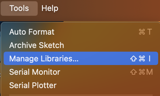
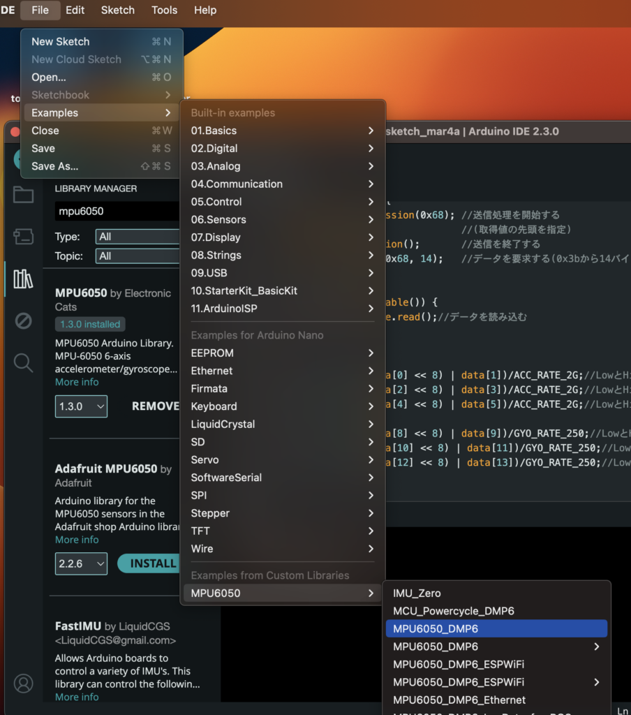
ArduinoのTools=>Manage Librariesを開いてください。
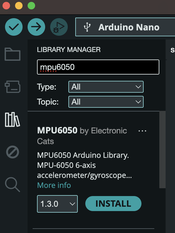
検索窓に「MPU6050」と打ち込んでみてください。そうするとMPU6050 by ElectronicCatsという項目が出てくると思うのでINSTALLを押してください。
インストールが終わったら、File => Examples => MPU6050=> MPU6050_DMP6 を開いてみてください。
3.3 コード
以下のコードが表示されると思います。こちらをArduinoに書き込んでみましょう。
// I2C device class (I2Cdev) demonstration Arduino sketch for MPU6050 class using DMP (MotionApps v2.0)
// 6/21/2012 by Jeff Rowberg <jeff@rowberg.net>
// Updates should (hopefully) always be available at https://github.com/jrowberg/i2cdevlib
//
// Changelog:
//      2019-07-08 - Added Auto Calibration and offset generator
//		   - and altered FIFO retrieval sequence to avoid using blocking code
//      2016-04-18 - Eliminated a potential infinite loop
//      2013-05-08 - added seamless Fastwire support
//                 - added note about gyro calibration
//      2012-06-21 - added note about Arduino 1.0.1 + Leonardo compatibility error
//      2012-06-20 - improved FIFO overflow handling and simplified read process
//      2012-06-19 - completely rearranged DMP initialization code and simplification
//      2012-06-13 - pull gyro and accel data from FIFO packet instead of reading directly
//      2012-06-09 - fix broken FIFO read sequence and change interrupt detection to RISING
//      2012-06-05 - add gravity-compensated initial reference frame acceleration output
//                 - add 3D math helper file to DMP6 example sketch
//                 - add Euler output and Yaw/Pitch/Roll output formats
//      2012-06-04 - remove accel offset clearing for better results (thanks Sungon Lee)
//      2012-06-01 - fixed gyro sensitivity to be 2000 deg/sec instead of 250
//      2012-05-30 - basic DMP initialization working

/* ============================================
I2Cdev device library code is placed under the MIT license
Copyright (c) 2012 Jeff Rowberg

Permission is hereby granted, free of charge, to any person obtaining a copy
of this software and associated documentation files (the "Software"), to deal
in the Software without restriction, including without limitation the rights
to use, copy, modify, merge, publish, distribute, sublicense, and/or sell
copies of the Software, and to permit persons to whom the Software is
furnished to do so, subject to the following conditions:

The above copyright notice and this permission notice shall be included in
all copies or substantial portions of the Software.

THE SOFTWARE IS PROVIDED "AS IS", WITHOUT WARRANTY OF ANY KIND, EXPRESS OR
IMPLIED, INCLUDING BUT NOT LIMITED TO THE WARRANTIES OF MERCHANTABILITY,
FITNESS FOR A PARTICULAR PURPOSE AND NONINFRINGEMENT. IN NO EVENT SHALL THE
AUTHORS OR COPYRIGHT HOLDERS BE LIABLE FOR ANY CLAIM, DAMAGES OR OTHER
LIABILITY, WHETHER IN AN ACTION OF CONTRACT, TORT OR OTHERWISE, ARISING FROM,
OUT OF OR IN CONNECTION WITH THE SOFTWARE OR THE USE OR OTHER DEALINGS IN
THE SOFTWARE.
===============================================
*/

// I2Cdev and MPU6050 must be installed as libraries, or else the .cpp/.h files
// for both classes must be in the include path of your project
#include "I2Cdev.h"

#include "MPU6050_6Axis_MotionApps20.h"
//#include "MPU6050.h" // not necessary if using MotionApps include file

// Arduino Wire library is required if I2Cdev I2CDEV_ARDUINO_WIRE implementation
// is used in I2Cdev.h
#if I2CDEV_IMPLEMENTATION == I2CDEV_ARDUINO_WIRE
    #include "Wire.h"
#endif

// class default I2C address is 0x68
// specific I2C addresses may be passed as a parameter here
// AD0 low = 0x68 (default for SparkFun breakout and InvenSense evaluation board)
// AD0 high = 0x69
MPU6050 mpu;
//MPU6050 mpu(0x69); // <-- use for AD0 high

/* =========================================================================
   NOTE: In addition to connection 3.3v, GND, SDA, and SCL, this sketch
   depends on the MPU-6050's INT pin being connected to the Arduino's
   external interrupt #0 pin. On the Arduino Uno and Mega 2560, this is
   digital I/O pin 2.
 * ========================================================================= */

/* =========================================================================
   NOTE: Arduino v1.0.1 with the Leonardo board generates a compile error
   when using Serial.write(buf, len). The Teapot output uses this method.
   The solution requires a modification to the Arduino USBAPI.h file, which
   is fortunately simple, but annoying. This will be fixed in the next IDE
   release. For more info, see these links:

   http://arduino.cc/forum/index.php/topic,109987.0.html
   http://code.google.com/p/arduino/issues/detail?id=958
 * ========================================================================= */


// uncomment "OUTPUT_READABLE_QUATERNION" if you want to see the actual
// quaternion components in a [w, x, y, z] format (not best for parsing
// on a remote host such as Processing or something though)
//#define OUTPUT_READABLE_QUATERNION

// uncomment "OUTPUT_READABLE_EULER" if you want to see Euler angles
// (in degrees) calculated from the quaternions coming from the FIFO.
// Note that Euler angles suffer from gimbal lock (for more info, see
// http://en.wikipedia.org/wiki/Gimbal_lock)
//#define OUTPUT_READABLE_EULER

// uncomment "OUTPUT_READABLE_YAWPITCHROLL" if you want to see the yaw/
// pitch/roll angles (in degrees) calculated from the quaternions coming
// from the FIFO. Note this also requires gravity vector calculations.
// Also note that yaw/pitch/roll angles suffer from gimbal lock (for
// more info, see: http://en.wikipedia.org/wiki/Gimbal_lock)
#define OUTPUT_READABLE_YAWPITCHROLL

// uncomment "OUTPUT_READABLE_REALACCEL" if you want to see acceleration
// components with gravity removed. This acceleration reference frame is
// not compensated for orientation, so +X is always +X according to the
// sensor, just without the effects of gravity. If you want acceleration
// compensated for orientation, us OUTPUT_READABLE_WORLDACCEL instead.
//#define OUTPUT_READABLE_REALACCEL

// uncomment "OUTPUT_READABLE_WORLDACCEL" if you want to see acceleration
// components with gravity removed and adjusted for the world frame of
// reference (yaw is relative to initial orientation, since no magnetometer
// is present in this case). Could be quite handy in some cases.
//#define OUTPUT_READABLE_WORLDACCEL

// uncomment "OUTPUT_TEAPOT" if you want output that matches the
// format used for the InvenSense teapot demo
//#define OUTPUT_TEAPOT


#define INTERRUPT_PIN 2  // use pin 2 on Arduino Uno & most boards
#define LED_PIN 13 // (Arduino is 13, Teensy is 11, Teensy++ is 6)
bool blinkState = false;

// MPU control/status vars
bool dmpReady = false;  // set true if DMP init was successful
uint8_t mpuIntStatus;   // holds actual interrupt status byte from MPU
uint8_t devStatus;      // return status after each device operation (0 = success, !0 = error)
uint16_t packetSize;    // expected DMP packet size (default is 42 bytes)
uint16_t fifoCount;     // count of all bytes currently in FIFO
uint8_t fifoBuffer[64]; // FIFO storage buffer

// orientation/motion vars
Quaternion q;           // [w, x, y, z]         quaternion container
VectorInt16 aa;         // [x, y, z]            accel sensor measurements
VectorInt16 aaReal;     // [x, y, z]            gravity-free accel sensor measurements
VectorInt16 aaWorld;    // [x, y, z]            world-frame accel sensor measurements
VectorFloat gravity;    // [x, y, z]            gravity vector
float euler[3];         // [psi, theta, phi]    Euler angle container
float ypr[3];           // [yaw, pitch, roll]   yaw/pitch/roll container and gravity vector

// packet structure for InvenSense teapot demo
uint8_t teapotPacket[14] = { '$', 0x02, 0,0, 0,0, 0,0, 0,0, 0x00, 0x00, '\r', '\n' };


// ================================================================
// ===               INTERRUPT DETECTION ROUTINE                ===
// ================================================================

volatile bool mpuInterrupt = false;     // indicates whether MPU interrupt pin has gone high
void dmpDataReady() {
    mpuInterrupt = true;
}


// ================================================================
// ===                      INITIAL SETUP                       ===
// ================================================================

void setup() {
    // join I2C bus (I2Cdev library doesn't do this automatically)
    #if I2CDEV_IMPLEMENTATION == I2CDEV_ARDUINO_WIRE
        Wire.begin();
        Wire.setClock(400000); // 400kHz I2C clock. Comment this line if having compilation difficulties
    #elif I2CDEV_IMPLEMENTATION == I2CDEV_BUILTIN_FASTWIRE
        Fastwire::setup(400, true);
    #endif

    // initialize serial communication
    // (115200 chosen because it is required for Teapot Demo output, but it's
    // really up to you depending on your project)
    Serial.begin(115200);
    while (!Serial); // wait for Leonardo enumeration, others continue immediately

    // NOTE: 8MHz or slower host processors, like the Teensy @ 3.3V or Arduino
    // Pro Mini running at 3.3V, cannot handle this baud rate reliably due to
    // the baud timing being too misaligned with processor ticks. You must use
    // 38400 or slower in these cases, or use some kind of external separate
    // crystal solution for the UART timer.

    // initialize device
    Serial.println(F("Initializing I2C devices..."));
    mpu.initialize();
    pinMode(INTERRUPT_PIN, INPUT);

    // verify connection
    Serial.println(F("Testing device connections..."));
    Serial.println(mpu.testConnection() ? F("MPU6050 connection successful") : F("MPU6050 connection failed"));

    // wait for ready
    Serial.println(F("\nSend any character to begin DMP programming and demo: "));
    while (Serial.available() && Serial.read()); // empty buffer
    while (!Serial.available());                 // wait for data
    while (Serial.available() && Serial.read()); // empty buffer again

    // load and configure the DMP
    Serial.println(F("Initializing DMP..."));
    devStatus = mpu.dmpInitialize();

    // supply your own gyro offsets here, scaled for min sensitivity
    mpu.setXGyroOffset(220);
    mpu.setYGyroOffset(76);
    mpu.setZGyroOffset(-85);
    mpu.setZAccelOffset(1788); // 1688 factory default for my test chip

    // make sure it worked (returns 0 if so)
    if (devStatus == 0) {
        // Calibration Time: generate offsets and calibrate our MPU6050
        mpu.CalibrateAccel(6);
        mpu.CalibrateGyro(6);
        mpu.PrintActiveOffsets();
        // turn on the DMP, now that it's ready
        Serial.println(F("Enabling DMP..."));
        mpu.setDMPEnabled(true);

        // enable Arduino interrupt detection
        Serial.print(F("Enabling interrupt detection (Arduino external interrupt "));
        Serial.print(digitalPinToInterrupt(INTERRUPT_PIN));
        Serial.println(F(")..."));
        attachInterrupt(digitalPinToInterrupt(INTERRUPT_PIN), dmpDataReady, RISING);
        mpuIntStatus = mpu.getIntStatus();

        // set our DMP Ready flag so the main loop() function knows it's okay to use it
        Serial.println(F("DMP ready! Waiting for first interrupt..."));
        dmpReady = true;

        // get expected DMP packet size for later comparison
        packetSize = mpu.dmpGetFIFOPacketSize();
    } else {
        // ERROR!
        // 1 = initial memory load failed
        // 2 = DMP configuration updates failed
        // (if it's going to break, usually the code will be 1)
        Serial.print(F("DMP Initialization failed (code "));
        Serial.print(devStatus);
        Serial.println(F(")"));
    }

    // configure LED for output
    pinMode(LED_PIN, OUTPUT);
}


// ================================================================
// ===                    MAIN PROGRAM LOOP                     ===
// ================================================================

void loop() {
    // if programming failed, don't try to do anything
    if (!dmpReady) return;
    // read a packet from FIFO
    if (mpu.dmpGetCurrentFIFOPacket(fifoBuffer)) { // Get the Latest packet
        #ifdef OUTPUT_READABLE_QUATERNION
            // display quaternion values in easy matrix form: w x y z
            mpu.dmpGetQuaternion(&q, fifoBuffer);
            Serial.print("quat\t");
            Serial.print(q.w);
            Serial.print("\t");
            Serial.print(q.x);
            Serial.print("\t");
            Serial.print(q.y);
            Serial.print("\t");
            Serial.println(q.z);
        #endif

        #ifdef OUTPUT_READABLE_EULER
            // display Euler angles in degrees
            mpu.dmpGetQuaternion(&q, fifoBuffer);
            mpu.dmpGetEuler(euler, &q);
            Serial.print("euler\t");
            Serial.print(euler[0] * 180/M_PI);
            Serial.print("\t");
            Serial.print(euler[1] * 180/M_PI);
            Serial.print("\t");
            Serial.println(euler[2] * 180/M_PI);
        #endif

        #ifdef OUTPUT_READABLE_YAWPITCHROLL
            // display Euler angles in degrees
            mpu.dmpGetQuaternion(&q, fifoBuffer);
            mpu.dmpGetGravity(&gravity, &q);
            mpu.dmpGetYawPitchRoll(ypr, &q, &gravity);
            Serial.print("ypr\t");
            Serial.print(ypr[0] * 180/M_PI);
            Serial.print("\t");
            Serial.print(ypr[1] * 180/M_PI);
            Serial.print("\t");
            Serial.println(ypr[2] * 180/M_PI);
        #endif

        #ifdef OUTPUT_READABLE_REALACCEL
            // display real acceleration, adjusted to remove gravity
            mpu.dmpGetQuaternion(&q, fifoBuffer);
            mpu.dmpGetAccel(&aa, fifoBuffer);
            mpu.dmpGetGravity(&gravity, &q);
            mpu.dmpGetLinearAccel(&aaReal, &aa, &gravity);
            Serial.print("areal\t");
            Serial.print(aaReal.x);
            Serial.print("\t");
            Serial.print(aaReal.y);
            Serial.print("\t");
            Serial.println(aaReal.z);
        #endif

        #ifdef OUTPUT_READABLE_WORLDACCEL
            // display initial world-frame acceleration, adjusted to remove gravity
            // and rotated based on known orientation from quaternion
            mpu.dmpGetQuaternion(&q, fifoBuffer);
            mpu.dmpGetAccel(&aa, fifoBuffer);
            mpu.dmpGetGravity(&gravity, &q);
            mpu.dmpGetLinearAccel(&aaReal, &aa, &gravity);
            mpu.dmpGetLinearAccelInWorld(&aaWorld, &aaReal, &q);
            Serial.print("aworld\t");
            Serial.print(aaWorld.x);
            Serial.print("\t");
            Serial.print(aaWorld.y);
            Serial.print("\t");
            Serial.println(aaWorld.z);
        #endif

        #ifdef OUTPUT_TEAPOT
            // display quaternion values in InvenSense Teapot demo format:
            teapotPacket[2] = fifoBuffer[0];
            teapotPacket[3] = fifoBuffer[1];
            teapotPacket[4] = fifoBuffer[4];
            teapotPacket[5] = fifoBuffer[5];
            teapotPacket[6] = fifoBuffer[8];
            teapotPacket[7] = fifoBuffer[9];
            teapotPacket[8] = fifoBuffer[12];
            teapotPacket[9] = fifoBuffer[13];
            Serial.write(teapotPacket, 14);
            teapotPacket[11]++; // packetCount, loops at 0xFF on purpose
        #endif

        // blink LED to indicate activity
        blinkState = !blinkState;
        digitalWrite(LED_PIN, blinkState);
    }
}
書き込みが終わったらシリアルモニタを開いてみましょう。
baudrateは115200に設定してください。
なんでも良いので文字を入力してエンターを押してみましょう!そうするとxyzの角度が取得できていることが確認できます!
(注意):変な文字が出た方へ。baudrateを 115200に設定し忘れています!
以上のように、ライブラリを活用することで簡単にセンサの姿勢を取得することができました!このようにライブラリを上手く活用すれば、さまざまなセンサを容易に使用できるようになります。
※ 今回使用したセンサは、I2C(アイ・スクエアード・シー)接続のジャイロ・加速度センサです。このセンサの特徴は、DMP(Digital Motion Processor)機能を使うことで、補正済みのデータを簡単に取得できる点です。ジャイロ(角速度センサ)は温度によって特性が変化しやすく、またノイズも多いので、適切な処理が必要です。DMPを使用することで、センサから出力された6軸分のデータをもとに、姿勢や四元数を計算して得ることができます。
4. Processing
さて、ライブラリを使って加速度や角度を取り出すことができるようになりました。
ここからPC上の3DCGモデルとセンサ値を連動させることに挑戦していきます!(多くの人がここから詰まりました。最難関です。基本的にArduino IDEを使っている時はProcessingは停止させ、Processingを使っているときはArduino IDEを終了させておきましょう。)
ProcessingとArduinoを連動させて、以下のように実世界と仮想世界を繋ぎます!
Arduino IDE、Arduino本体、Processingのそれぞれの役割は以下のイメージ!
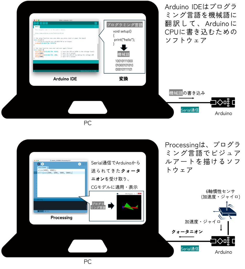
(注意)Processingについては今回深くは触れません。一先ずArduinoから送られてきたデータを3DCGとして簡単に表示できる環境と捉えておいてください。
4.1 Processingのダウンロード
まずはProcessingをダウンロードしていきましょう。

4.2 サンプルコードを動かしてみよう!
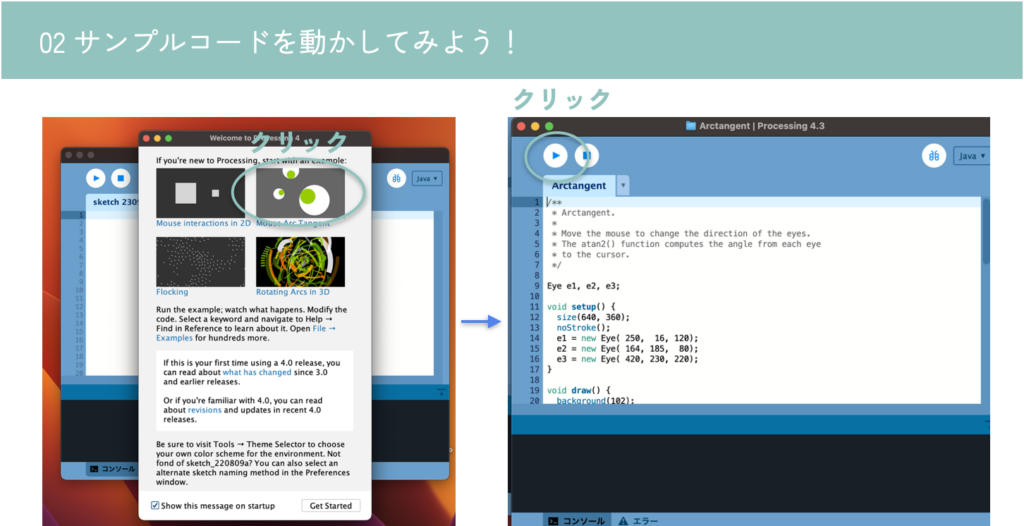
マウスを目玉が追っかけるようなデモアプリが立ち上がります。Processingはこのようなインタラクティブに反応するビジュアルアートを簡単に作ることができます。
(注意)この後、Processingを終了させてしまう場合があるので、アプリケーションの位置(Windowsならexeファイルなどの位置)を把握しておきましょう。
4.3 Processingの基礎を理解しよう!
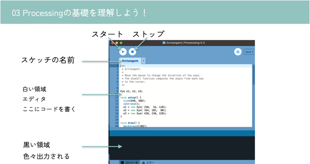
Arduino IDEを触る時は基本停止(ストップ)で。
4.4 teapot demoを動かしてみよう!
4.4.1 ToxicLibsのインストール
サンプルコードを正しく動作させるには、ライブラリであるToxicLibsがインストールされている必要があります。
https://github.com/postspectacular/toxiclibs/releases からzipファイルをダウンロードし、 [userdir]/Processing/librariesに解凍してください。(toxiclibs-complete-0021.zipね。Source codeじゃないよ)
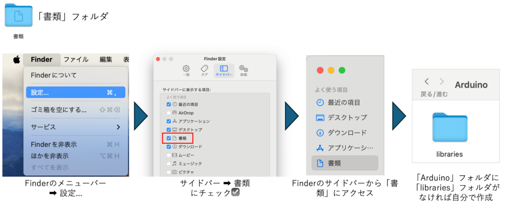
- Mac
- ユーザーディレクトリ下の「書類」フォルダの中にProcessingがあります。
- /Users/{yourname}/Documents/Processing/libraries の中に展開してください。
- Macで「書類」フォルダが見つからなかったら
- Windows
- ユーザーディレクトリ下の「\Documents\Processing\libraries」の中に展開してください。
- (注意)OneDriveと連携している関係でDocumentsが二つあるようです。必ずProcessingと紐づいている方へ展開してください。おそらく最初にOneDriveがついてる方。連動している場合はProcessingフォルダの中にlibrariesだけでなくexpamplesなど全部で4つほどフォルダがあるようです。
以下のフォルダをすべてProcessingのlibraries内にドラッグ&ドロップしてください。
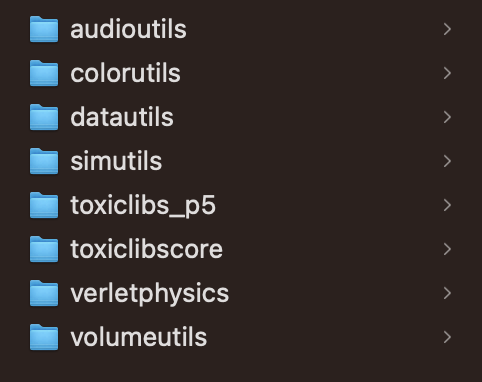
(注意)toxiclibs-complete-0021の中にあるすべてのフォルダをlibrariesの中においてください。何名かが〜\libraries\toxiclibs-complete-0021\audioutils などとしてました。正しくは〜\libraries\audioutils です。
移動後、一度Processingを再起動しておきましょう。
(注意)Processingを再起動しないとライブラリ読み込めずエラー出ます。ToxiclibsSupportがないよ、と出ます。
(注意)Macの方は、フォームを閉じるだけではなくて、アプリを終了させること!フォームを閉じて開くだけだと再起動になりません。
4.4.2 Processingのteapotサンプルコードを開く
Arduinoから送られてきた姿勢データを表示するためのProcessingのサンプルコードの場所は以下の通り。
- Mac
- ユーザーディレクトリ下の「書類」フォルダの中にあります。
- /Users/{yourname}/Documents/Arduino/libraries/MPU6050/examples/MPU6050_DMP6/Processing/MPUTeapot/MPUTeapot.pde を開いてください。
- Windows
- ユーザーディレクトリ下の「/Documents/Arduino/libraries/MPU6050/examples/MPU6050_DMP6/Processing/MPUTeapot/MPUTeapot.pde」の中にあるはずです(「書類」フォルダ)。
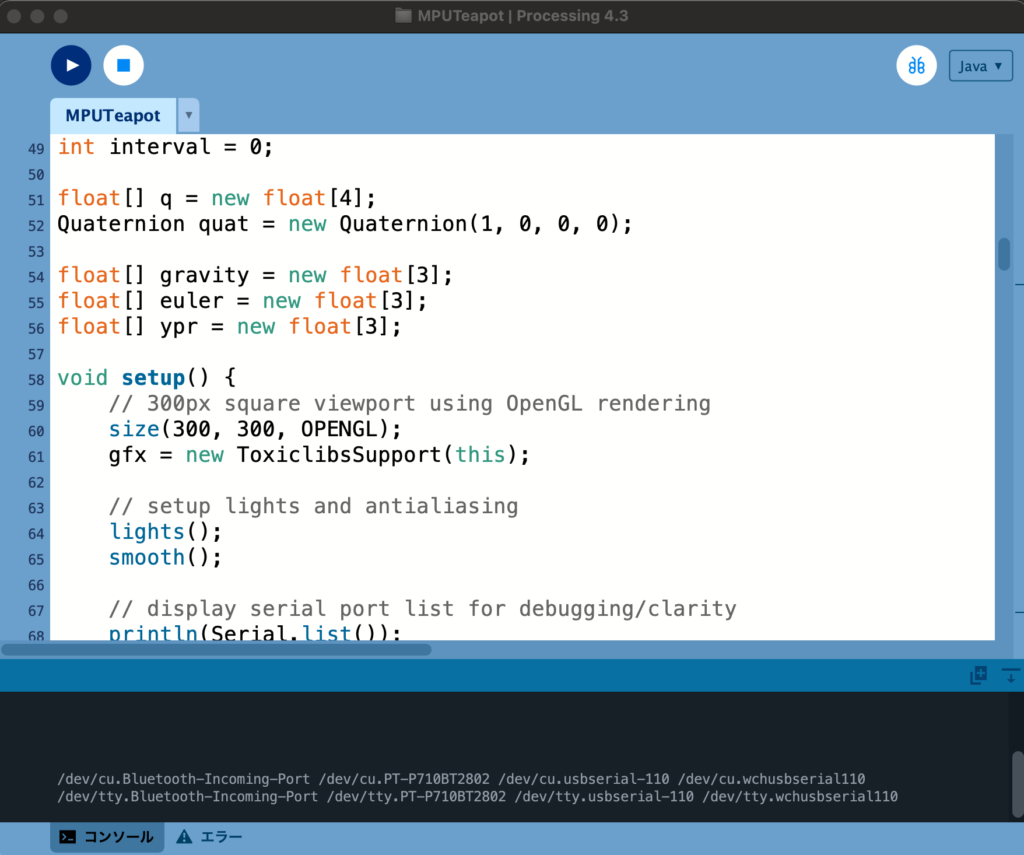
以下のようなコードですよね。実行してみましょう。
// I2C device class (I2Cdev) demonstration Processing sketch for MPU6050 DMP output
// 6/20/2012 by Jeff Rowberg <jeff@rowberg.net>
// Updates should (hopefully) always be available at https://github.com/jrowberg/i2cdevlib
//
// Changelog:
//     2012-06-20 - initial release

/* ============================================
I2Cdev device library code is placed under the MIT license
Copyright (c) 2012 Jeff Rowberg

Permission is hereby granted, free of charge, to any person obtaining a copy
of this software and associated documentation files (the "Software"), to deal
in the Software without restriction, including without limitation the rights
to use, copy, modify, merge, publish, distribute, sublicense, and/or sell
copies of the Software, and to permit persons to whom the Software is
furnished to do so, subject to the following conditions:

The above copyright notice and this permission notice shall be included in
all copies or substantial portions of the Software.

THE SOFTWARE IS PROVIDED "AS IS", WITHOUT WARRANTY OF ANY KIND, EXPRESS OR
IMPLIED, INCLUDING BUT NOT LIMITED TO THE WARRANTIES OF MERCHANTABILITY,
FITNESS FOR A PARTICULAR PURPOSE AND NONINFRINGEMENT. IN NO EVENT SHALL THE
AUTHORS OR COPYRIGHT HOLDERS BE LIABLE FOR ANY CLAIM, DAMAGES OR OTHER
LIABILITY, WHETHER IN AN ACTION OF CONTRACT, TORT OR OTHERWISE, ARISING FROM,
OUT OF OR IN CONNECTION WITH THE SOFTWARE OR THE USE OR OTHER DEALINGS IN
THE SOFTWARE.
===============================================
*/

import processing.serial.*;
import processing.opengl.*;
import toxi.geom.*;
import toxi.processing.*;

// NOTE: requires ToxicLibs to be installed in order to run properly.
// 1. Download from https://github.com/postspectacular/toxiclibs/releases
// 2. Extract into [userdir]/Processing/libraries
//    (location may be different on Mac/Linux)
// 3. Run and bask in awesomeness

ToxiclibsSupport gfx;

Serial port;                         // The serial port
char[] teapotPacket = new char[14];  // InvenSense Teapot packet
int serialCount = 0;                 // current packet byte position
int synced = 0;
int interval = 0;

float[] q = new float[4];
Quaternion quat = new Quaternion(1, 0, 0, 0);

float[] gravity = new float[3];
float[] euler = new float[3];
float[] ypr = new float[3];

void setup() {
    // 300px square viewport using OpenGL rendering
    size(300, 300, OPENGL);
    gfx = new ToxiclibsSupport(this);

    // setup lights and antialiasing
    lights();
    smooth();

    // display serial port list for debugging/clarity
    println(Serial.list());

    // get the first available port (use EITHER this OR the specific port code below)
    String portName = Serial.list()[0];

    // get a specific serial port (use EITHER this OR the first-available code above)
    //String portName = "COM4";

    // open the serial port
    port = new Serial(this, portName, 115200);

    // send single character to trigger DMP init/start
    // (expected by MPU6050_DMP6 example Arduino sketch)
    port.write('r');
    port.write('r');
}

void draw() {
    if (millis() - interval > 1000) {
        // resend single character to trigger DMP init/start
        // in case the MPU is halted/reset while applet is running
        port.write('r');
        interval = millis();
    }

    // black background
    background(0);

    // translate everything to the middle of the viewport
    pushMatrix();
    translate(width / 2, height / 2);

    // 3-step rotation from yaw/pitch/roll angles (gimbal lock!)
    // ...and other weirdness I haven't figured out yet
    //rotateY(-ypr[0]);
    //rotateZ(-ypr[1]);
    //rotateX(-ypr[2]);

    // toxiclibs direct angle/axis rotation from quaternion (NO gimbal lock!)
    // (axis order [1, 3, 2] and inversion [-1, +1, +1] is a consequence of
    // different coordinate system orientation assumptions between Processing
    // and InvenSense DMP)
    float[] axis = quat.toAxisAngle();
    rotate(axis[0], -axis[1], axis[3], axis[2]);

    // draw main body in red
    fill(255, 0, 0, 200);
    box(10, 10, 200);

    // draw front-facing tip in blue
    fill(0, 0, 255, 200);
    pushMatrix();
    translate(0, 0, -120);
    rotateX(PI/2);
    drawCylinder(0, 20, 20, 8);
    popMatrix();

    // draw wings and tail fin in green
    fill(0, 255, 0, 200);
    beginShape(TRIANGLES);
    vertex(-100,  2, 30); vertex(0,  2, -80); vertex(100,  2, 30);  // wing top layer
    vertex(-100, -2, 30); vertex(0, -2, -80); vertex(100, -2, 30);  // wing bottom layer
    vertex(-2, 0, 98); vertex(-2, -30, 98); vertex(-2, 0, 70);  // tail left layer
    vertex( 2, 0, 98); vertex( 2, -30, 98); vertex( 2, 0, 70);  // tail right layer
    endShape();
    beginShape(QUADS);
    vertex(-100, 2, 30); vertex(-100, -2, 30); vertex(  0, -2, -80); vertex(  0, 2, -80);
    vertex( 100, 2, 30); vertex( 100, -2, 30); vertex(  0, -2, -80); vertex(  0, 2, -80);
    vertex(-100, 2, 30); vertex(-100, -2, 30); vertex(100, -2,  30); vertex(100, 2,  30);
    vertex(-2,   0, 98); vertex(2,   0, 98); vertex(2, -30, 98); vertex(-2, -30, 98);
    vertex(-2,   0, 98); vertex(2,   0, 98); vertex(2,   0, 70); vertex(-2,   0, 70);
    vertex(-2, -30, 98); vertex(2, -30, 98); vertex(2,   0, 70); vertex(-2,   0, 70);
    endShape();

    popMatrix();
}

void serialEvent(Serial port) {
    interval = millis();
    while (port.available() > 0) {
        int ch = port.read();

        if (synced == 0 && ch != '$') return;   // initial synchronization - also used to resync/realign if needed
        synced = 1;
        print ((char)ch);

        if ((serialCount == 1 && ch != 2)
            || (serialCount == 12 && ch != '\r')
            || (serialCount == 13 && ch != '\n'))  {
            serialCount = 0;
            synced = 0;
            return;
        }

        if (serialCount > 0 || ch == '$') {
            teapotPacket[serialCount++] = (char)ch;
            if (serialCount == 14) {
                serialCount = 0; // restart packet byte position

                // get quaternion from data packet
                q[0] = ((teapotPacket[2] << 8) | teapotPacket[3]) / 16384.0f;
                q[1] = ((teapotPacket[4] << 8) | teapotPacket[5]) / 16384.0f;
                q[2] = ((teapotPacket[6] << 8) | teapotPacket[7]) / 16384.0f;
                q[3] = ((teapotPacket[8] << 8) | teapotPacket[9]) / 16384.0f;
                for (int i = 0; i < 4; i++) if (q[i] >= 2) q[i] = -4 + q[i];

                // set our toxilibs quaternion to new data
                quat.set(q[0], q[1], q[2], q[3]);

                /*
                // below calculations unnecessary for orientation only using toxilibs

                // calculate gravity vector
                gravity[0] = 2 * (q[1]*q[3] - q[0]*q[2]);
                gravity[1] = 2 * (q[0]*q[1] + q[2]*q[3]);
                gravity[2] = q[0]*q[0] - q[1]*q[1] - q[2]*q[2] + q[3]*q[3];

                // calculate Euler angles
                euler[0] = atan2(2*q[1]*q[2] - 2*q[0]*q[3], 2*q[0]*q[0] + 2*q[1]*q[1] - 1);
                euler[1] = -asin(2*q[1]*q[3] + 2*q[0]*q[2]);
                euler[2] = atan2(2*q[2]*q[3] - 2*q[0]*q[1], 2*q[0]*q[0] + 2*q[3]*q[3] - 1);

                // calculate yaw/pitch/roll angles
                ypr[0] = atan2(2*q[1]*q[2] - 2*q[0]*q[3], 2*q[0]*q[0] + 2*q[1]*q[1] - 1);
                ypr[1] = atan(gravity[0] / sqrt(gravity[1]*gravity[1] + gravity[2]*gravity[2]));
                ypr[2] = atan(gravity[1] / sqrt(gravity[0]*gravity[0] + gravity[2]*gravity[2]));

                // output various components for debugging
                //println("q:\t" + round(q[0]*100.0f)/100.0f + "\t" + round(q[1]*100.0f)/100.0f + "\t" + round(q[2]*100.0f)/100.0f + "\t" + round(q[3]*100.0f)/100.0f);
                //println("euler:\t" + euler[0]*180.0f/PI + "\t" + euler[1]*180.0f/PI + "\t" + euler[2]*180.0f/PI);
                //println("ypr:\t" + ypr[0]*180.0f/PI + "\t" + ypr[1]*180.0f/PI + "\t" + ypr[2]*180.0f/PI);
                */
            }
        }
    }
}

void drawCylinder(float topRadius, float bottomRadius, float tall, int sides) {
    float angle = 0;
    float angleIncrement = TWO_PI / sides;
    beginShape(QUAD_STRIP);
    for (int i = 0; i < sides + 1; ++i) {
        vertex(topRadius*cos(angle), 0, topRadius*sin(angle));
        vertex(bottomRadius*cos(angle), tall, bottomRadius*sin(angle));
        angle += angleIncrement;
    }
    endShape();

    // If it is not a cone, draw the circular top cap
    if (topRadius != 0) {
        angle = 0;
        beginShape(TRIANGLE_FAN);

        // Center point
        vertex(0, 0, 0);
        for (int i = 0; i < sides + 1; i++) {
            vertex(topRadius * cos(angle), 0, topRadius * sin(angle));
            angle += angleIncrement;
        }
        endShape();
    }

    // If it is not a cone, draw the circular bottom cap
    if (bottomRadius != 0) {
        angle = 0;
        beginShape(TRIANGLE_FAN);

        // Center point
        vertex(0, tall, 0);
        for (int i = 0; i < sides + 1; i++) {
            vertex(bottomRadius * cos(angle), tall, bottomRadius * sin(angle));
            angle += angleIncrement;
        }
        endShape();
    }
}
実行すると、serial portの名前一覧がコンソール(黒い部分)に表示されると思います。
(注意)Windowsの場合は 「COM44」など一つだけ出てくる場合が多いです。そのように表示された場合は特に値は変更せず、println(Serial.list()); を // でコメントアウトしておいてください。
(注意)Serial Busyなどのエラーが出る場合は、Arudino IDEをすべて閉じましょう。

表示順に0から番号が振ってあると思ってください。
例えば上記の場合は、
/dev/cu.Bluetooth-Incoming-Port が 0
/dev/cu.PT-P710BT2802 が 1
/dev/cu.usbserial-110 が 2
/dev/cu.wchusbserial110 が 3
/dev/tty.Bluetooth-Incoming-Port が 4
/dev/tty.PT-P710BT2802 が 5
/dev/tty.usbserial-110 が 6
/dev/tty-wchusbserial110 が 7
です。
void setup()内にある
String portName = Serial.list()[0];の0を、Arduinoに接続されたシリアルポート(大体 /dev/cu.usbserial-110とかだと思います)に該当する番号に変更してください(71行目)。
私の場合は /dev/cu.usbserial-110 なので 2 としました。
またその直下に、
String portName = Serial.list()[2];
println(Serial.list()[2]);とでも追記しておくと、狙ったシリアルポートの名前をうまく取得できているかコンソール画面で確認できて安心です。尚、println(Serial.list()); を // でコメントアウトしておいてください。
4.4.3 Arduinoの再書き込み(Arduino IDE)
次にArduinoのコードをArduino IDEで一部書き直す必要があります。おそらくデフォルトでは
103行目あたり) #define OUTPUT_READABLE_YAWPITCHROLL
が実行されるようになっていますが、こちらをコメントアウトしてください。//を先頭に書き込みます。
(注意)Macの場合は Command + F Windowsの場合は Ctrl + F を押せば検索できるって知ってました?いろいろなところで使えるショートカットキーなので覚えておきましょう。このショートカットキーを使えばすぐに上記の該当箇所を見つけられます。
(注意)あれ、さっきのArduinoのコードどこいったっけ…?という方。Arduino IDEのFile => Examples => MPU6050=> MPU6050_DMP6 を開くとコード出てきます。もしくは、(Mac)/Documents/Arduino/libraries/MPU6050/examples/MPU6050_DMP6/MPU6050_DMP6.ino を開いてください。(Windows)ユーザーディレクトリ下の「/Documents/Arduino/libraries/MPU6050/examples/MPU6050_DMP6/MPU6050_DMP6.inoを開いてください。
// uncomment "OUTPUT_READABLE_YAWPITCHROLL" if you want to see the yaw/
// pitch/roll angles (in degrees) calculated from the quaternions coming
// from the FIFO. Note this also requires gravity vector calculations.
// Also note that yaw/pitch/roll angles suffer from gimbal lock (for
// more info, see: http://en.wikipedia.org/wiki/Gimbal_lock)
// #define OUTPUT_READABLE_YAWPITCHROLL
そして、以下をコメントアウトします。//を取り除きます。
120行目あたり)// #define OUTPUT_TEAPOT
// uncomment "OUTPUT_TEAPOT" if you want output that matches the
// format used for the InvenSense teapot demo
#define OUTPUT_TEAPOT
その部分を変更したらもう一度Arduinoに書き込みましょう!
(注意)なぜか書き込めない人。一度Arudinoからケーブルを抜き、もう一度接続し直してみてください。これでエラーなくなる方結構いました。
(注意)Serial Busyなど出る方、Processingを実行したままにしていませんか?Processingを停止させましょう。
4.4.4 実行
さて、ここまで準備が整ったらあとは、Arduino IDEを閉じて、Processingのコードを実行するのみです!以下のように、センサと3DCGが連動しましたか? (注:Processingが動作開始するまでに10秒程度時間がかかるので、ちょっと待ってから動かしてみましょう!)
(注意)フォームが複数立ち上がっているせいで、「No connection established Compilation error: No connection established」などのエラーが出る方、Arduino IDEを一度終了させましょう。Macの場合はフォームを閉じるだけでなく、上メニューからか、下のアイコンを右クリックしてアプリを終了させましょう。
5. 研究事例
6軸慣性センサについても、設置場所を工夫した多様な研究事例が報告されています。
首元に薄く貼れば発話認識も可能です。
Derma: 皮膚運動計測によるサイレントスピーチインタラクション
競技カルタで選手の手首に装着することで、どちらが札を取得したか検出するシステムも提案されています。
SwiftTouch:手首装着型センサを用いた競技かるたにおける札取得者判定システム
2024/03/04 土田