目次
1. MPU-6050を使って1軸の値を取得してみよう!
1.1 材料
- Arduino Nano
- ブレッドボード
- USBケーブル
- MPU6050
- ジャンパーワイヤ
MPU6050は、加速度センサとジャイロスコープ(角速度センサ)を一体化したセンサです。このデバイスは、3軸(x,y,z軸)の加速度と3軸(x,y,z軸)の角速度の両方を測定できるため、6軸慣性センサとも呼ばれます。このセンサは、モーショントラッキングや位置追跡に使用される他、スマートフォン、タブレット、ドローン、ロボットなど、さまざまなデバイスに搭載されています。
現実世界の動きと加速度、ジャイロと理解するにはこちらの動画がわかりやすいです。時間ある際に覗いてみてください。
加速度センサの原理
加速度センサは様々な種類が存在しますが、ピエゾ抵抗型について簡単に説明します。加速度センサにはピエゾ抵抗と呼ばれる抵抗が使われていて、力が加わるとその抵抗値が変化する性質を持っています。
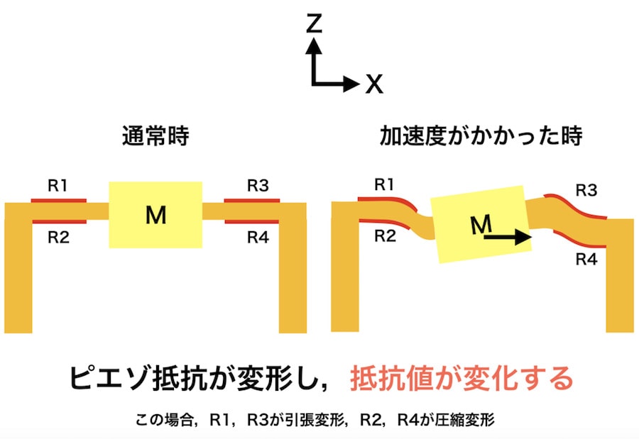
- 図の左側では、加速度がかかっていない通常の状態が示されています。この状態では、抵抗R1、R2、R3、R4に大きな変化はありません。ピエゾ抵抗は安定しており、抵抗値も変わりません。
- 図の右側では、加速度がかかったときの様子が示されています。加速度がかかると、質量Mが動き、それに伴って抵抗R1、R3が引っ張られ、R2、R4が圧縮されます。
- R1とR3 は引っ張られることで抵抗値が増加し、R2とR4 は圧縮されることで抵抗値が減少します。
このように、加速度がかかることで各抵抗の値が変化し、その変化を電気信号として検出することで、加速度の大きさや方向を計測することができます。
ジャイロセンサの原理
ジャイロセンサは、物体の回転や傾きを検出するセンサです。基本的な原理は、回転する力(角速度)を検出することにあります。内部にある小さな振動体が回転することで、その動きを電気信号に変換し、回転の方向や速度を測定します。
詳しくはこちらがわかりやすいです。
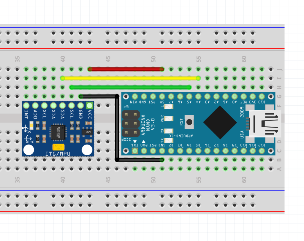
1.2 ブレッドボード図
それでは、以下のようにMPU-6050とArduinoを繋げてみましょう。
| MPU-6050 | Arduino |
| GND | GND |
| VCC | 5V |
| SDA | A4 |
| SCL | A5 |
実際の写真は以下の通り。
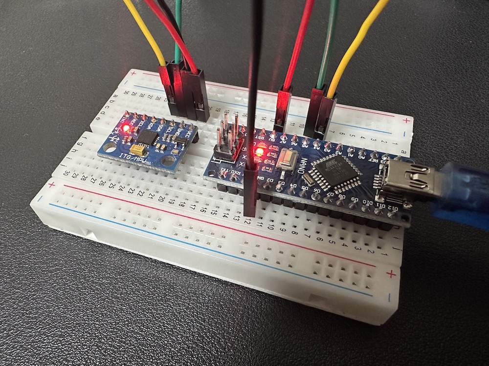
注:加速度センサを折り曲げる必要はありません。挿さればそれでOKです。
1.3 コード
Arduinoのコードは以下の通り。忘れず書き込みましょう。
//S0211_SAMPLE01
#include <Wire.h>

volatile uint8_t data[14]; //センサからのデータ格納用配列
volatile int16_t ax = 0;   //出力データ(生値)

void setup() {
  Serial.begin(9600);//シリアル通信を開始する
  Wire.begin();//I2C通信を開始する

  Wire.beginTransmission(0x68);//送信処理を開始する(0x68がセンサーのアドレス)
  Wire.write(0x6b);            //レジスタ「0x6b」(動作状変数)を指定
  Wire.write(0x00);            //0x00を指定(ON)
  Wire.endTransmission();      //送信を終了する
}

void loop() {
  MPU_DATAGET();
  Serial.print("ax: ");
  Serial.println(ax);
  delay(100);
}

void MPU_DATAGET() {
  Wire.beginTransmission(0x68); //送信処理を開始する
  Wire.write(0x3b);             //(取得値の先頭を指定)
  Wire.endTransmission();       //送信を終了する
  Wire.requestFrom(0x68, 14);   //データを要求する(0x3bから14バイトが6軸の値)

  uint8_t i = 0;
  while (Wire.available()) {
    data[i++] = Wire.read();//データを読み込む
  }


  ax = (data[0] << 8) | data[1];//LowとHighを連結して、値を取得する

}
それでは値をSerial Monitorで確認してみましょう!
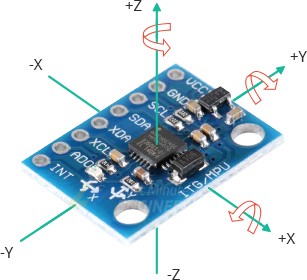
センサをx方向に振ってみるとx軸の加速度データが取れていることを確認できましたか?
y方向やz方向に振るとあまり値が変化しないかと思います.(注:加速度値なため回転は取れません。)
※ 0が返ってくる場合はセンサの故障を疑ってください
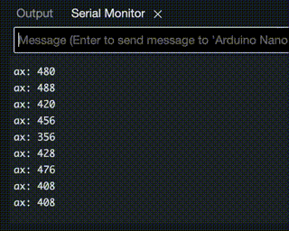
(注意):出力に文字列「ax:」が含まれるためSerial Plotterは起動しても反応しません!
2. MPU-6050を使って6軸の値を取得してみよう!
参考:MPU6050をArduinoで使う②6軸分のデータを取得する
2.1 コード
1章と同様の回路構成のまま、コードのみ以下のように変更し、再度書き込みましょう。
//MPU6050 6軸分の角度・角速度を取得するサンプル
#include <Wire.h>
#define ACC_RATE_2G 1671.8 // 加速度(2G)用の変換係数(生値→[m/s2]) ※32767/2/9.8
#define GYO_RATE_250 131.1 // 角速度(250[deg/s])用の変換係数(生値→[deg/s]) ※32767/250
volatile uint8_t data[14]; //センサからのデータ格納用配列
volatile float ax = 0; //出力データ(X軸加速度)
volatile float ay = 0; //出力データ(Y軸加速度)
volatile float az = 0; //出力データ(Z軸加速度)
volatile float rx = 0; //出力データ(X軸角速度)
volatile float ry = 0; //出力データ(Y軸角速度)
volatile float rz = 0; //出力データ(Z軸角速度)
void setup() {
Serial.begin(9600);//シリアル通信を開始する
Wire.begin();//I2C通信を開始する
i2cWriteReg(0x68,0x6b,0x00); //センサーをONにする
i2cWriteReg(0x68,0x1b,0x00); //角速度レンジ設定(±250[deg/s])
i2cWriteReg(0x68,0x1c,0x00); //加速度レンジ設定(±2G)
}
void loop() {
MPU_DATAGET();
Serial.print("ax: ");
Serial.print(ax);
Serial.print("\tay: ");
Serial.print(ay);
Serial.print("\taz: ");
Serial.print(az);
Serial.print("\trx: ");
Serial.print(rx);
Serial.print("\try: ");
Serial.print(ry);
Serial.print("\trz: ");
Serial.println(rz);
delay(100);
}
void MPU_DATAGET() {
Wire.beginTransmission(0x68); //送信処理を開始する
Wire.write(0x3b); //(取得値の先頭を指定)
Wire.endTransmission(); //送信を終了する
Wire.requestFrom(0x68, 14); //データを要求する(0x3bから14バイトが6軸の値)
uint8_t i = 0;
while (Wire.available()) {
data[i++] = Wire.read();//データを読み込む
}
ax = (float)((data[0] << 8) | data[1])/ACC_RATE_2G;//LowとHighを連結して、値を取得する
ay = (float)((data[2] << 8) | data[3])/ACC_RATE_2G;//LowとHighを連結して、値を取得する
az = (float)((data[4] << 8) | data[5])/ACC_RATE_2G;//LowとHighを連結して、値を取得する
rx = (float)((data[8] << 8) | data[9])/GYO_RATE_250;//LowとHighを連結して、値を取得する
ry = (float)((data[10] << 8) | data[11])/GYO_RATE_250;//LowとHighを連結して、値を取得する
rz = (float)((data[12] << 8) | data[13])/GYO_RATE_250;//LowとHighを連結して、値を取得する
}
//レジスタ書き込み
void i2cWriteReg(uint8_t ad, uint8_t reg, volatile uint8_t data) {
Wire.beginTransmission(ad); //送信処理を開始する
Wire.write(reg); //レジスタを指定
Wire.write(data); //データを書き込み
Wire.endTransmission(); //送信を終了する
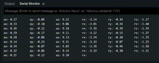
}それでは値をSerial Monitorで確認してみましょう!
先ほどと同様にセンサをx方向に振ってみる他、軸を意識しながら回転させてみてください。
自身の動作と値の変化の連動を確認できましたか?
3. MPU-6050を使って姿勢を取得し表示させてみよう!
参考:MPU6050をArduinoで使う③ライブラリを使う
(注意)このあたりから多くの方が詰まり始めました。タスクをスキップしないよう注意を払いましょう。
ここまでで、センサから最低限のデータ出力ができるようになりました。理想としては、自分で一連のプロセスをこなせるようになり、6軸の値を基にセンサの姿勢を取得し表示させることができれば良いのですが、非常に難しいです。そこで「ライブラリ」を使用することで、自分でコードを書くことなく、簡単かつ正確にデータの取得と表示を行うことができます。今回は、ライブラリを使ってデータを取得し、さらにProcessingで3Dモデルを表示するところまでを進めたいと思います。
3.1 ライブラリとは
自転車を組み立てる時、レンチやドライバーなどの道具が必要ですよね?プログラミングでも、ある特定のことをするためには、たくさんの小さな命令やコードが必要になります。でも、いちいち自分で全部の道具を作るのは大変ですよね。
ここで「ライブラリ」の出番です!ライブラリは、あらかじめたくさんのコードや機能が組み込まれている「プログラミングの道具箱」のようなものです。例えば、数学の問題を解くための公式が詰まった本や、絵を描くときに使う色鉛筆セットのようなものです。
プログラミングで何かをしたい時、その「道具箱」から必要なツールを取り出して、自分のプロジェクトに使うことができます。これにより、すべてを一から作る手間が省け、もっと簡単に、早くプログラムを作ることができます。
つまり、ライブラリを使うということは、プロの工具を借りて、自分の作業を楽にするようなものです!
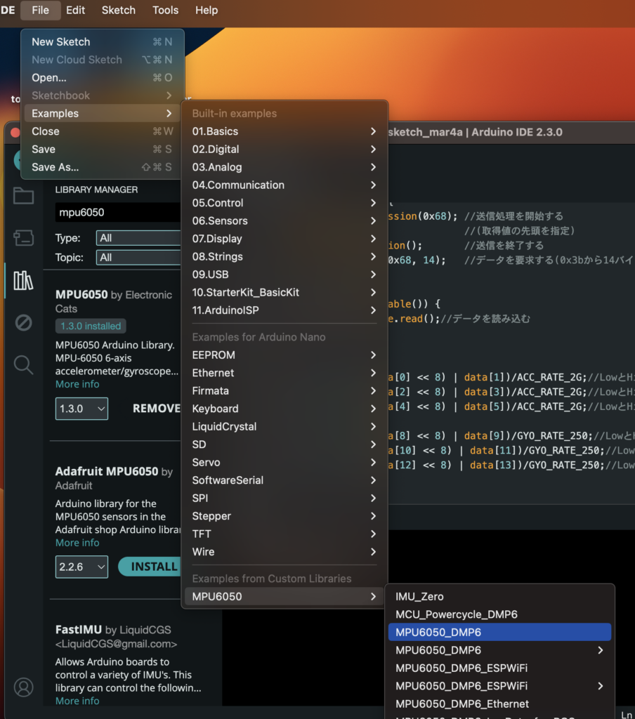
3.2 ライブラリのインストール
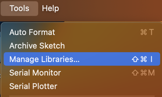
ArduinoのTools=>Manage Librariesを開いてください。
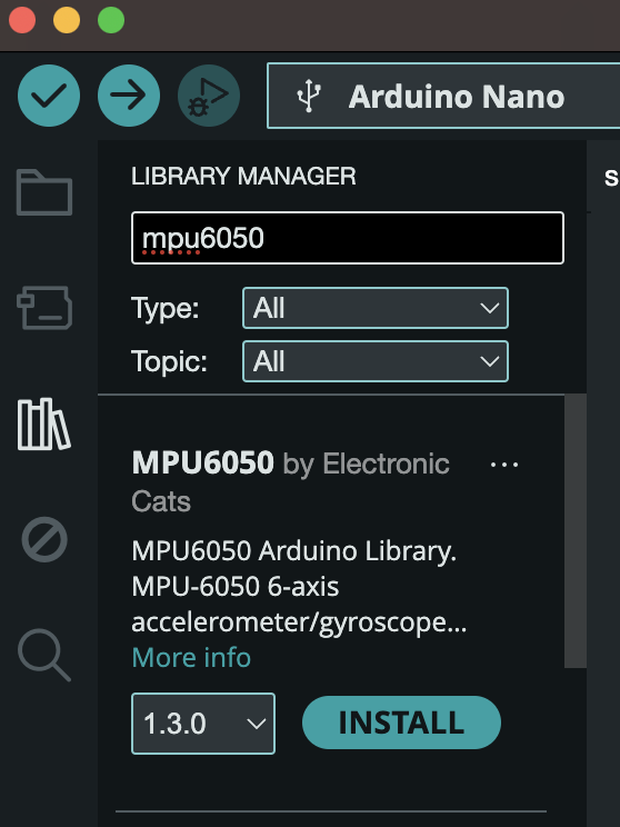
検索窓に「MPU6050」と打ち込んでみてください。そうするとMPU6050 by ElectronicCatsという項目が出てくると思うのでINSTALLを押してください。
インストールが終わったら、File => Examples => MPU6050=> MPU6050_DMP6 を開いてみてください。
3.3 コード
このようなコード(MPU6050_DMP6_for_Arduino.txt)が表示されると思います。Arduinoに書き込んでみましょう。
※書き込みエラーが出た際に、加速度センサとArduinoのGNDとの接続を切る(ピンを抜いてあげる)とうまく書き込める場合があります。
書き込みが終わったらシリアルモニタを開いてみましょう。
baudrateは115200に設定してください。
なんでも良いので文字を入力してエンターを押してみましょう!そうするとxyzの角度が取得できていることが確認できます!
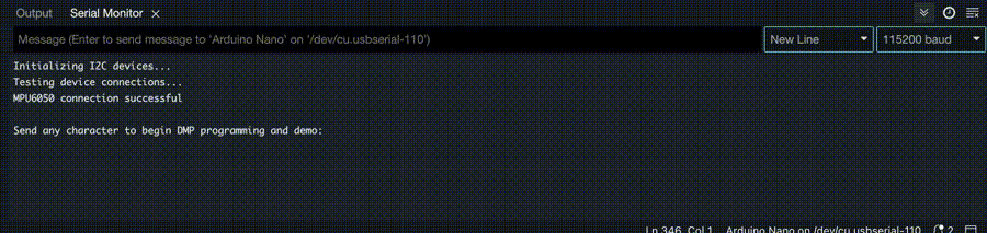
(注意):変な文字が出た方へ。baudrateを 115200に設定し忘れています!
以上のように、ライブラリを活用することで簡単にセンサの姿勢を取得することができました!このようにライブラリを上手く活用すれば、さまざまなセンサを容易に使用できるようになります。
※ 今回使用したセンサは、I2C(アイ・スクエアード・シー)接続のジャイロ・加速度センサです。このセンサの特徴は、DMP(Digital Motion Processor)機能を使うことで、補正済みのデータを簡単に取得できる点です。ジャイロ(角速度センサ)は温度によって特性が変化しやすく、またノイズも多いので、適切な処理が必要です。DMPを使用することで、センサから出力された6軸分のデータをもとに、姿勢や四元数を計算して得ることができます。
4. Processing
さて、ライブラリを使って加速度や角度を取り出すことができるようになりました。
ここからPC上の3DCGモデルとセンサ値を連動させることに挑戦していきます!(多くの人がここから詰まりました。最難関です。基本的にArduino IDEを使っている時はProcessingは停止させ、Processingを使っているときはArduino IDEを終了させておきましょう。)
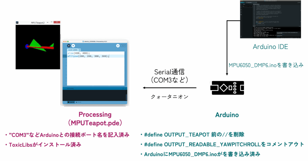
ProcessingとArduinoを連動させて、以下のように実世界と仮想世界を繋ぎます!
Arduino IDE、Arduino本体、Processingのそれぞれの役割は以下のイメージ!
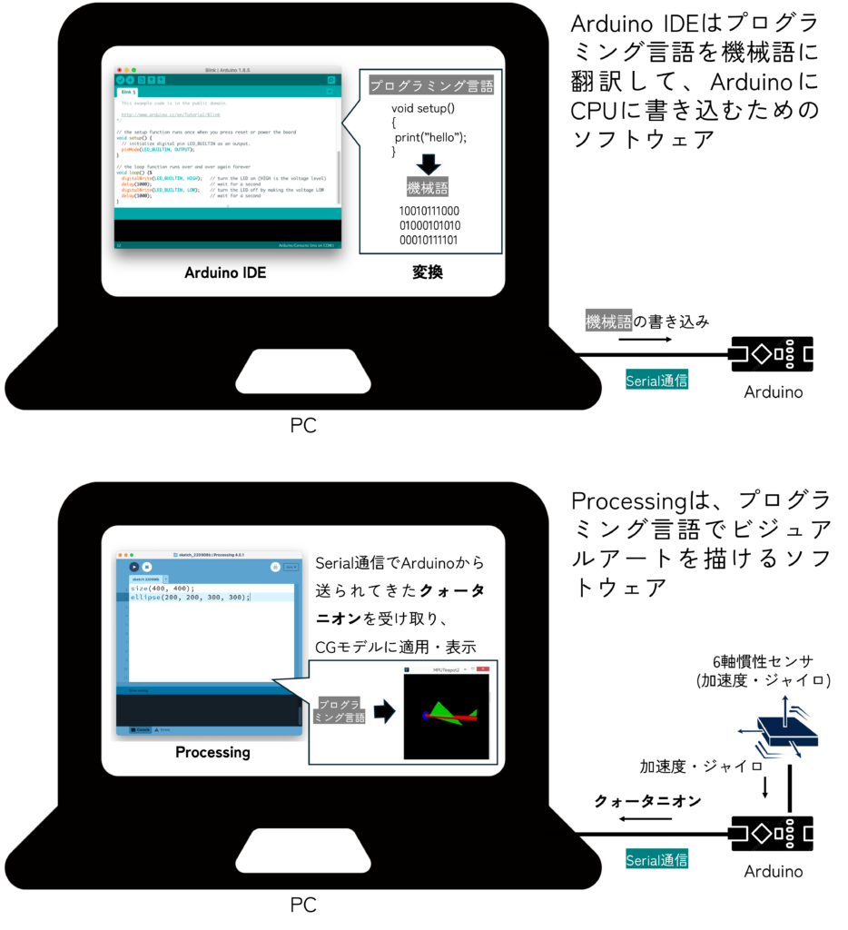
(注意)Processingについては今回深くは触れません。一先ずArduinoから送られてきたデータを3DCGとして簡単に表示できる環境と捉えておいてください。
4.1 Processingのダウンロード
大まかな流れは以下の動画を参考に
Windows:https://youtu.be/naU_JeT9IF0
まずはProcessingをダウンロードしていきましょう。

4.2 サンプルコードを動かしてみよう!
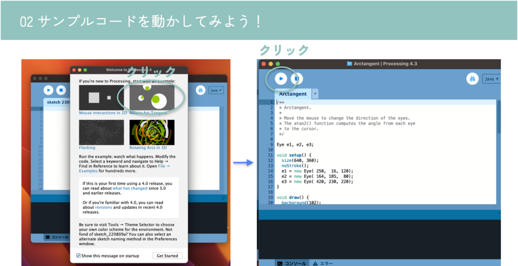
マウスを目玉が追っかけるようなデモアプリが立ち上がります。Processingはこのようなインタラクティブに反応するビジュアルアートを簡単に作ることができます。
(注意)この後、Processingを終了させてしまう場合があるので、アプリケーションの位置(Windowsならexeファイルなどの位置)を把握しておきましょう。
4.3 Processingの基礎を理解しよう!
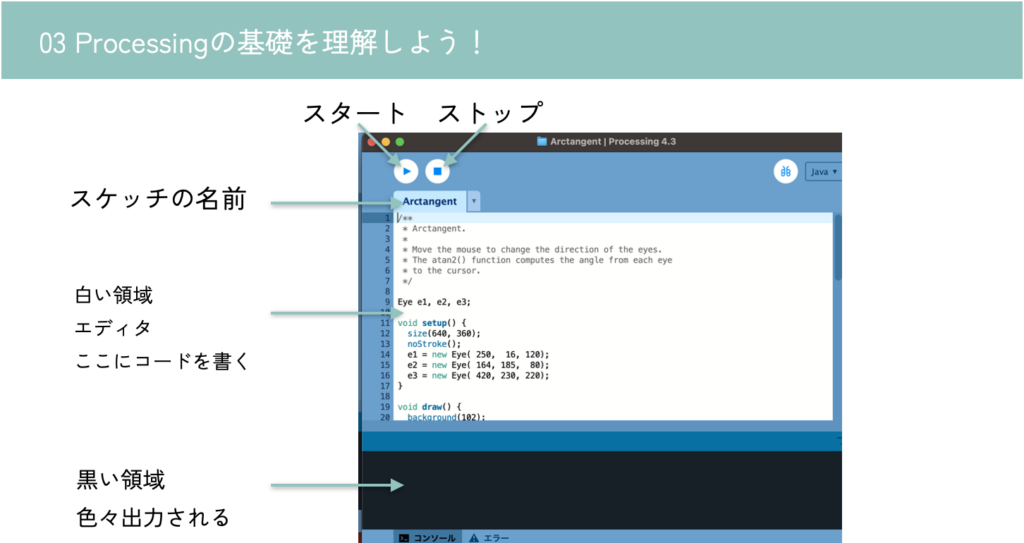
Arduino IDEを触る時は基本停止(ストップ)しましょう。
4.4 teapot demoを動かしてみよう!
大体の流れは以下の動画を参考にしてください
Windows:https://youtu.be/esWALMx6r9o
4.4.1 ToxicLibsのインストール
サンプルコードを正しく動作させるには、ライブラリであるToxicLibsがインストールされている必要があります。
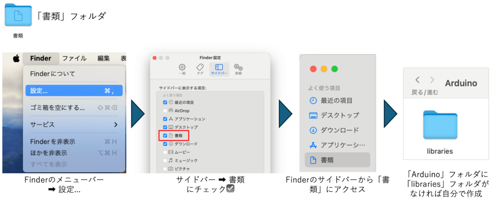
https://github.com/postspectacular/toxiclibs/releases からzipファイルをダウンロードし、 [userdir]/Processing/librariesに解凍してください。(toxiclibs-complete-0021.zipです。Source codeじゃないですよ)
- Mac
- ユーザーディレクトリ下の「書類」フォルダの中にProcessingがあります。
- /Users/{yourname}/Documents/Processing/libraries の中に展開してください。
- Macで「書類」フォルダが見つからなかったら
- Windows
- ユーザーディレクトリ下の「\Documents\Processing\libraries」の中に展開してください。
- (注意)OneDriveと連携している関係でDocumentsが二つあるようです。必ずProcessingと紐づいている方へ展開してください。おそらく最初にOneDriveがついてる方。連動している場合はProcessingフォルダの中にlibrariesだけでなくexpamplesなど全部で4つほどフォルダがあるようです。
以下のフォルダをすべてProcessingのlibraries内にドラッグ&ドロップしてください。
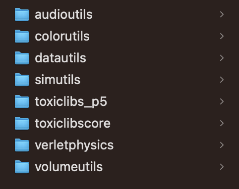
(注意)toxiclibs-complete-0021の中にあるすべてのフォルダをlibrariesの中においてください。何名かが〜\libraries\toxiclibs-complete-0021\audioutils などとしてました。正しくは〜\libraries\audioutils です。
移動後、一度Processingを再起動しておきましょう。
(注意)Processingを再起動しないとライブラリ読み込めずエラー出ます。ToxiclibsSupportがないよ、と出ます。
(注意)Macの方は、フォームを閉じるだけではなくて、アプリを終了させること!フォームを閉じて開くだけだと再起動になりません。
4.4.2 Processingのteapotサンプルコードを開く
Arduinoから送られてきた姿勢データを表示するためのProcessingのサンプルコードの場所は以下の通り。
- Mac
- ユーザーディレクトリ下の「書類」フォルダの中にあります。
- /Users/{yourname}/Documents/Arduino/libraries/MPU6050/examples/MPU6050_DMP6/Processing/MPUTeapot/MPUTeapot.pde を開いてください。
- Windows
- ユーザーディレクトリ下の「/Documents/Arduino/libraries/MPU6050/examples/MPU6050_DMP6/Processing/MPUTeapot/MPUTeapot.pde」の中にあるはずです(「書類」フォルダ)。
このようなコード(MPU6050_DMP6_teapot_for_Processing.txt)ですよね。実行してみましょう。
実行すると、serial portの名前一覧がコンソール(黒い部分)に表示されると思います。
(注意)Windowsの場合は 「COM3」など一つだけ出てくる場合が多いです。そのように表示された場合は特に値は変更せず、println(Serial.list()); を // でコメントアウトしておいてください。
(注意)Serial Busyなどのエラーが出る場合は、Arudino IDEをすべて閉じましょう。
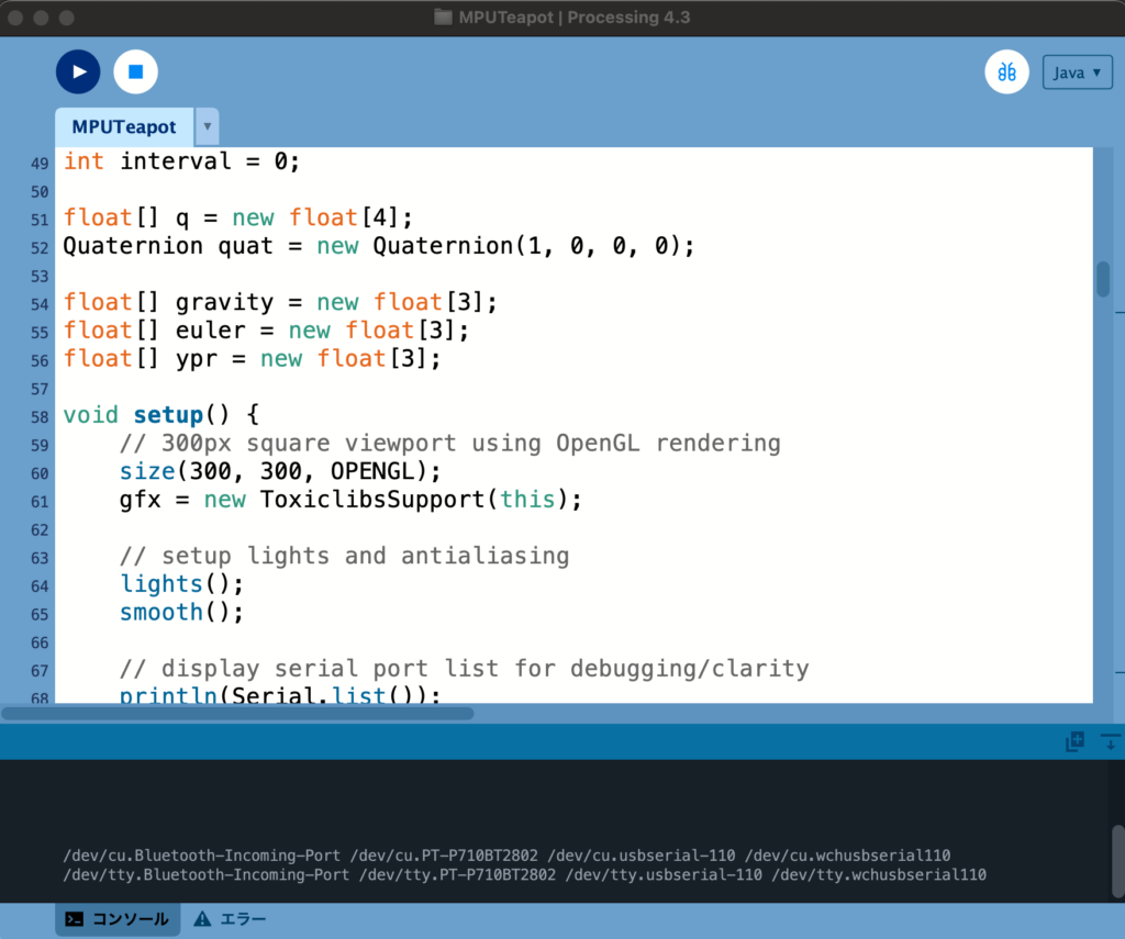

表示順に0から番号が振ってあると思ってください。
例えば上記の場合は、
/dev/cu.Bluetooth-Incoming-Port が 0
/dev/cu.PT-P710BT2802 が 1
/dev/cu.usbserial-110 が 2
/dev/cu.wchusbserial110 が 3
/dev/tty.Bluetooth-Incoming-Port が 4
/dev/tty.PT-P710BT2802 が 5
/dev/tty.usbserial-110 が 6
/dev/tty-wchusbserial110 が 7
です。
void setup()内にある
String portName = Serial.list()[0];の0を、Arduinoに接続されたシリアルポート(大体 /dev/cu.usbserial-110とかだと思います)に該当する番号に変更してください(71行目)。
私の場合は /dev/cu.usbserial-110 なので 2 としました。
またその直下に、
String portName = Serial.list()[2];
println(Serial.list()[2]);
とでも追記しておくと、狙ったシリアルポートの名前をうまく取得できているかコンソール画面で確認できて安心です。
4.4.3 Arduinoの再書き込み(Arduino IDE)
次にArduinoのコードをArduino IDEで一部書き直す必要があります。おそらくデフォルトでは
#define OUTPUT_READABLE_YAWPITCHROLL
が実行されるようになっていますが、こちらをコメントアウトしてください。//を先頭に書き込みます。
(注意)Macの場合は Command + F Windowsの場合は Ctrl + F を押せば検索できるって知ってました?いろいろなところで使えるショートカットキーなので覚えておきましょう。このショートカットキーを使えばすぐに上記の該当箇所を見つけられます。例えば「OUTPUT_READABLE」で検索してみましょう。
(注意)あれ、さっきのArduinoのコードどこいったっけ…?という方。Arduino IDEのFile => Examples => MPU6050=> MPU6050_DMP6 を開くとコード出てきます。もしくは、(Mac)/Documents/Arduino/libraries/MPU6050/examples/MPU6050_DMP6/MPU6050_DMP6.ino を開いてください。(Windows)ユーザーディレクトリ下の「/Documents/Arduino/libraries/MPU6050/examples/MPU6050_DMP6/MPU6050_DMP6.inoを開いてください。
// uncomment "OUTPUT_READABLE_YAWPITCHROLL" if you want to see the yaw/
// pitch/roll angles (in degrees) calculated from the quaternions coming
// from the FIFO. Note this also requires gravity vector calculations.
// Also note that yaw/pitch/roll angles suffer from gimbal lock (for
// more info, see: http://en.wikipedia.org/wiki/Gimbal_lock)
// #define OUTPUT_READABLE_YAWPITCHROLL
そして、以下をコメントアウトします。//を取り除きます。
// #define OUTPUT_TEAPOT
// uncomment "OUTPUT_TEAPOT" if you want output that matches the
// format used for the InvenSense teapot demo
#define OUTPUT_TEAPOTその部分を変更したらもう一度Arduinoに書き込みましょう!一応コメントアウト済みの最終版コード(MPU6050_DMP6_teapot_for_Arduino.txt)も置いておきますが、理解のために、自分でコメントアウトしたバージョンの使用をおススメします。
(注意)なぜか書き込めない人。一度Arudinoからケーブルを抜き、もう一度接続し直してみてください。これでエラーなくなる方結構いました。
(注意)なぜか書き込めない人。加速度センサとArduinoのGNDとの接続を切った状態(ピンを外した状態)で書き込んでみましょう。これでエラーなくなる方もいました。
(注意)Serial Busyなど出る方、Processingを実行したままにしていませんか?Processingを停止させましょう。
4.4.4 実行
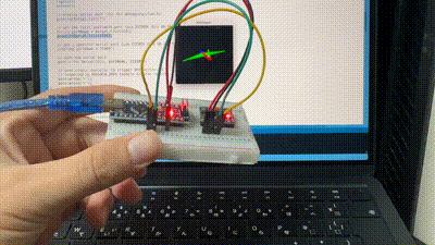
さて、ここまで準備が整ったらあとは、Arduino IDEを閉じて、Processingのコードを実行するのみです!以下のように、センサと3DCGが連動しましたか? (注:Processingが動作開始するまでに10秒程度時間がかかるので、ちょっと待ってから動かしてみましょう!)
(注意)フォームが複数立ち上がっているせいで、「No connection established Compilation error: No connection established」などのエラーが出る方、Arduino IDEを一度終了させましょう。Macの場合はフォームを閉じるだけでなく、上メニューからか、下のアイコンを右クリックしてアプリを終了させましょう。
5. 研究事例
6軸慣性センサについても、設置場所を工夫した多様な研究事例が報告されています。
首元に薄く貼れば発話認識も可能です。
Derma: 皮膚運動計測によるサイレントスピーチインタラクション
競技カルタで選手の手首に装着することで、どちらが札を取得したか検出するシステムも提案されています。
SwiftTouch:手首装着型センサを用いた競技かるたにおける札取得者判定システム
2024/03/04 土田
2025/07/29 土田 微修正